
09-对part7-bluetooth的翻译和搬运
所有非黑色的字体均为我自己添加
原文放在文章末尾
启动蓝牙
仅仅用一个UART连接的电脑来控制树莓派并不是很有趣.我们的Breakout游戏值得比它更好的控制器 -- 最好是无线的.
在这一部分中,我们设置了第二个UART来和树莓派板上的蓝牙调制调节器(modem)进行沟通.关于蓝牙的东西并不简单,但至少比USB简单.这就是我选择它的原因.
博通的固件
蓝牙调制调节器是一款博通公司的芯片(BCM43455),并且它在工作前需要加载专有的软件.我已经从蓝牙仓库(https://github.com/RPi-Distro/bluez-firmware/tree/master/broadcom)中取得了它们的 BCM4345C0.hcd 文件.
由于我们并没有任何文件系统,所以我们不能在运行时加载它,而是把它编译到我们的内核里.我们可以使用 objcopy来编译一个可以链接的 a.o 文件.我们在Makefile中添加这些行:
BCM4345C0.o : BCM4345C0.hcd
$(GCCPATH)/aarch64-none-elf-objcopy -I binary -O elf64-littleaarch64 -B aarch64 $< $@
我们也需要修改我们的 kernel8.img 依赖来包含新的 .o 文件
kernel8.img: boot.o $(OFILES) BCM4345C0.o
$(GCCPATH)/aarch64-none-elf-ld -nostdlib -nostartfiles boot.o $(OFILES) BCM4345C0.o -T link.ld -o kernel8.elf
$(GCCPATH)/aarch64-none-elf-objcopy -O binary kernel8.elf kernel8.img
如果你现在编译内核,你就会发现镜像文件变得非常大 -- 因为它包含了固件.你可以运行 objdump -x kernel8.elf 然后你可以在这里看见一些新的符号:
_binary_BCM4345C0_hcd_start
_binary_BCM4345C0_hcd_size
_binary_BCM4345C0_hcd_end
我们稍后将使用这些符号来引用C代码中的固件。
设置UART
看到我们的新 bt.c .现在我们将要关注 //UART0 这一节.大多数技术对你来讲都会很熟悉,因为这个硬件也是使用MMIO,并且我们要实现我们实现过的函数来进行一系列的debug工作.
为了在我们debug的同时使用蓝牙,我们将要重新映射GPIO引脚.30,31,32,33脚需要选择函数3来让我们访问CTS0, RTS0, TXD0 和 RXD0.你可以在 BCM2711 ARM 外设手册(https://datasheets.raspberrypi.com/bcm2711/bcm2711-peripherals.pdf)中读到关于它的一切.
我们已经有了 io.c 中的函数来做这些,所以我们把 gpio_useAsAlt3 的函数定义添加到 io.h 中来让我们从这里可以访问它.在 bt_init() 中,我们继续,并且重新映射GPIO引脚,然后冲刷接收缓冲区保证安全.在它后面写的MMIO代码,设置了115200的波特率和8-N-1的通讯(这里是1位起始位,8位数据位,没有奇偶校验的简写) -- 我们知道蓝牙调制调解器可以处理这些.可能最重要的要搞对的是这个:
mmio_write(ARM_UART0_CR, 0xB01);
它使能了串口(bit 0 置1),使能 TX和RX (bit 8 和 9 置1),并且把 RTS0 拉低(bit 11 置1) -- 非常重要,因为蓝牙调制调解器不会应答,除非它看见这个.我花了很多时间来解决这个问题.
我们可以使用UART来和蓝牙调制调解器通信了.
与蓝牙调制调解器通信
蓝牙规范是很繁重的,实现一个完全的驱动需要花上好些时间.我现在就要解决"证明生活".我们仍然有方法通过...(这句的翻译拿不准,原文为 I'll settle for "proof of life" for now. We still have a way to travel though...)
我们将要使用 HCI命令同蓝牙调制调解器通信.作为这个的介绍,我享受阅读TI HCI 文档(https://software-dl.ti.com/simplelink/esd/simplelink_cc13x2_sdk/1.60.00.29_new/exports/docs/ble5stack/vendor_specific_guide/BLE_Vendor_Specific_HCI_Guide/hci_interface.html)
bt_reset()只是调用 hci_Command,它又调用 hci_CommandBytes 来向UART传输字符从而告诉蓝牙芯片重置并且等待固件.这是一个和供应商有关的调用,所以你不会在任何地方找到文档.我使用树莓派Linux发行版中的以下文件对调用进行了反向工程:
https://github.com/raspberrypi/linux/blob/rpi-5.10.y/drivers/bluetooth/btbcm.c
https://github.com/raspberrypi/linux/blob/rpi-5.10.y/drivers/bluetooth/hci_bcm.c
https://github.com/raspberrypi/linux/blob/rpi-5.10.y/include/net/bluetooth/hci.h
hci_CommandBytes 之后在它返回成功前等待一个非常特殊的应答 -- "command complete" 应答.
加载固件
现在设备在等待.我们要向它发送我们内核中的固件字节.
void bt_loadfirmware()
{
volatile unsigned char empty[] = {};
if (hciCommand(OGF_VENDOR, COMMAND_LOAD_FIRMWARE, empty, 0)) uart_writeText("loadFirmware() failed\n");
extern unsigned char _binary_BCM4345C0_hcd_start[];
extern unsigned char _binary_BCM4345C0_hcd_size[];
unsigned int c=0;
unsigned int size = (long)&_binary_BCM4345C0_hcd_size;
unsigned char opcodebytes[2];
unsigned char length;
unsigned char *data = &(_binary_BCM4345C0_hcd_start[0]);
while (c < size) {
opcodebytes[0] = *data;
opcodebytes[1] = *(data+1);
length = *(data+2);
data += 3;
if (hciCommandBytes(opcodebytes, data, length)) {
uart_writeText("Firmware data load failed\n");
break;
}
data += length;
c += 3 + length;
}
wait_msec(0x100000);
}
首先,我们发送一条指令告诉芯片我们将要发送固件.你将会看到我们参考我们的新符号,它们指向我们的固件字节.我们现在知道了固件的大小,所以我们可以在其之上迭代.
固件只是一系列遵从这样的格式的HCI命令:
两字节操作符
一字节告诉我们后面跟着的数据的长度
相应长度字节的数据
我们进行的时候要检查每个命令是否成功,等待1秒然后返回.如果它正确运行,我们就加载好了固件,可以准备蓝牙通讯了.
我选择实现了 bd_setbaud() 和 bt_setbdaddr(). 这个设置了蓝牙调制调解器的通话速率(就像我们在串口的例子中所做的那样),和其独特的蓝牙设备地址(https://macaddresschanger.com/what-is-bluetooth-address-BD_ADDR)
建造一座埃迪斯通灯塔
可能可以建造的最简单的蓝牙设备就是"灯塔".它只是发布了少量的数据,任何经过的接收者都能看到这些数据.一个典型的用法就是为了基于位置的视场营销目的而发布的网络URL.
谷歌定义了埃迪斯通格式(https://en.wikipedia.org/wiki/Eddystone_(Google)),它被广泛的采用.我们将要在这个例子里面实现它.这是我们需要完成的:
设置LE事件掩膜来确保蓝牙控制器可以被所有到来的事件中断
设置广播参数
设置广播数据
启动广播
我的大部分学习都是由markfirmware的代码(https://github.com/markfirmware/zig-bare-metal-raspberry-pi/blob/master/src/ble.zig)引导的.我着重阅读了相关蓝牙标准( https://www.bluetooth.com/specifications/specs/core-specification-5-2/)的章节,而不是盲目的把代码粘贴到我的代码中.我推荐你也这么做,如果你同样对这里如何运行感兴趣的话.
当构建广播数据的时候,我推荐阅读PiMyLifeUp的文章(https://pimylifeup.com/raspberry-pi-eddystone-beacon/).
为了测试代码,确保 run_eddystone() 在内核中没有被注释掉,而不是 run_search() (我们将要在 part8-breakout-ble中对run_search() 做更详细的探讨)
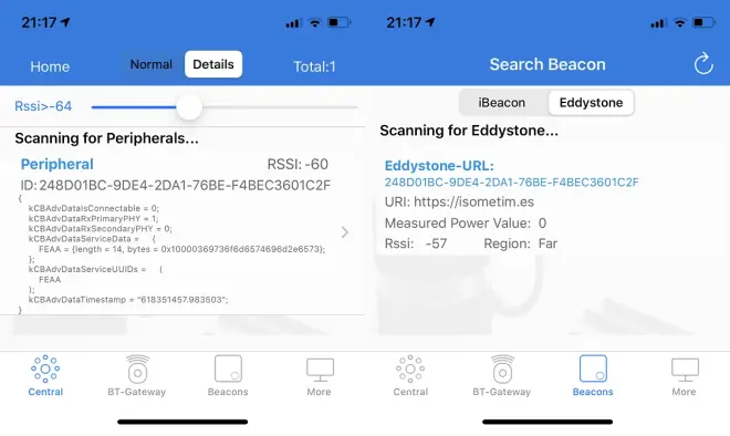
构建并运行后,我使用eBeacon iPhone应用程序检查我的Eddystone信标是否在广播。下面的截图显示了我发布的URL:

Getting Bluetooth up
Controlling the RPi4 solely via a UART-connected laptop is not much fun. Our Breakout game deserves a better controller than that - ideally a wireless one.
In this part, we set up a second UART to communicate with the RPi4's onboard Bluetooth modem. There is nothing simple about Bluetooth, but it is at least simpler than USB, and that's the reason I've chosen to pursue it.
The Broadcom firmware
The Bluetooth modem is a Broadcom chip (BCM43455), and it needs to be loaded with proprietary software before it's useful to us. I have taken their _BCM4345C0.hcd_ file from the [Bluez repo](https://github.com/RPi-Distro/bluez-firmware/tree/master/broadcom).
As we don't yet have any filesystem, we won't be able to load this at runtime, so instead we'll need to build it into our kernel. We can use `objcopy` to build a _.o_ file that we can link. We add these lines to _Makefile_:
```c
BCM4345C0.o : BCM4345C0.hcd
$(GCCPATH)/aarch64-none-elf-objcopy -I binary -O elf64-littleaarch64 -B aarch64 $< $@
```
We also need to modify our `kernel8.img` dependencies to include our new _.o_ file:
```c
kernel8.img: boot.o $(OFILES) BCM4345C0.o
$(GCCPATH)/aarch64-none-elf-ld -nostdlib -nostartfiles boot.o $(OFILES) BCM4345C0.o -T link.ld -o kernel8.elf
$(GCCPATH)/aarch64-none-elf-objcopy -O binary kernel8.elf kernel8.img
```
If you build the kernel now, you'll see that the new image is much bigger - because it contains the firmware bytes. You can run `objdump -x kernel8.elf`, and you'll also see a few new symbols in there:
* _binary_BCM4345C0_hcd_start
* _binary_BCM4345C0_hcd_size
* _binary_BCM4345C0_hcd_end
We'll use these symbols later to reference the firmware from our C code.
Setting up the UART
Look at our new _bt.c_. We'll focus on the `// UART0` section for now. A lot of the techniques will be familiar to you as this hardware also uses the MMIO technique, and we're implementing a lot of the same functions that we did to get our serial debug working.
To use Bluetooth at the same time as our serial debug, we'll need to remap some GPIO pins. Pins 30, 31, 32 and 33 will all need to take on their _alternate function 3_ to give us access to CTS0, RTS0, TXD0 and RXD0. You can read all about this in Section 5.3 of the [BCM2711 ARM Peripherals document](https://www.raspberrypi.org/documentation/hardware/raspberrypi/bcm2711/rpi_DATA_2711_1p0.pdf).
We already have a function in _io.c_ to do this, and so we add the function definition of `gpio_useAsAlt3` to _io.h_ to give us access to it from here. In `bt_init()`, we go ahead and remap the GPIO pins, then flush the receive buffer just to be safe. The MMIO writes which follow, set us up for 115200 baud and [8-N-1 communication](https://en.wikipedia.org/wiki/8-N-1) - we know the Bluetooth modem can cope with this. Perhaps the most important line to get right was this one:
```c
mmio_write(ARM_UART0_CR, 0xB01);
```
It enables the UART (bit 0 on), enables TX & RX (bits 8 & 9 on), and drives RTS0 low (bit 11 on) - very important as the Bluetooth modem will sit unresponsive until it sees this. **I lost a lot of time figuring this one out.**
We should now be able to talk to the Bluetooth modem over our new UART.
Talking to the Bluetooth modem
The Bluetooth spec is massive, and to implement a full driver would take a long while. I'll settle for "proof of life" for now. We still have a way to travel though...
We talk to the Bluetooth modem using **HCI commands**. I enjoyed reading the [TI HCI docs](http://software-dl.ti.com/simplelink/esd/simplelink_cc13x2_sdk/1.60.00.29_new/exports/docs/ble5stack/vendor_specific_guide/BLE_Vendor_Specific_HCI_Guide/hci_interface.html) as an intro to this.
`bt_reset()` simply calls `hci_Command`, which in turn called `hci_CommandBytes` to write the bytes out to the UART that tell the Bluetooth chip to reset and await firmware. This is a vendor-specific call, so you won't find it documented anywhere. I reverse-engineered the calls using the following files from the Raspberry Pi Linux distribution:
* https://github.com/raspberrypi/linux/blob/rpi-5.10.y/drivers/bluetooth/btbcm.c
* https://github.com/raspberrypi/linux/blob/rpi-5.10.y/drivers/bluetooth/hci_bcm.c
* https://github.com/raspberrypi/linux/blob/rpi-5.10.y/include/net/bluetooth/hci.h
`hci_CommandBytes` then waits for a very specific response before it returns successfully - the "command complete" response.
Loading the firmware
Now the device is waiting. We need to send it the firmware bytes we included in our kernel:
```c
void bt_loadfirmware()
{
volatile unsigned char empty[] = {};
if (hciCommand(OGF_VENDOR, COMMAND_LOAD_FIRMWARE, empty, 0)) uart_writeText("loadFirmware() failed\n");
extern unsigned char _binary_BCM4345C0_hcd_start[];
extern unsigned char _binary_BCM4345C0_hcd_size[];
unsigned int c=0;
unsigned int size = (long)&_binary_BCM4345C0_hcd_size;
unsigned char opcodebytes[2];
unsigned char length;
unsigned char *data = &(_binary_BCM4345C0_hcd_start[0]);
while (c < size) {
opcodebytes[0] = *data;
opcodebytes[1] = *(data+1);
length = *(data+2);
data += 3;
if (hciCommandBytes(opcodebytes, data, length)) {
uart_writeText("Firmware data load failed\n");
break;
}
data += length;
c += 3 + length;
}
wait_msec(0x100000);
}
```
First, we send a command to tell the chip that we're about send the firmware. You'll see that we then reference our new symbols, which point us at our firmware bytes. We now know the size of the firmware, and so we iterate over it.
The firmware is simply a sequence of HCI commands following this format:
* 2 bytes of opcode
* 1 byte that tells us the length of the data to follow
* _length_ bytes of data
We check each HCI command succeeds as we go, wait a second and then return. If it runs without error then we've loaded our firmware and we're ready to start some Bluetooth communications.
I've then chosen to implement `bd_setbaud()` and `bt_setbdaddr()`. This sets the speed at which the Bluetooth modem will talk (much like we did in our UART examples) and also its unique [Bluetooth Device Address](https://macaddresschanger.com/what-is-bluetooth-address-BD_ADDR).
Building an Eddystone beacon
Perhaps the simplest Bluetooth device to build is a "beacon". It simply advertises a small amount of data publicly, such that any passing receivers can view the data. A typical use case is to advertise a web URL for location-based marketing purposes.
Google defined the [Eddystone format](https://en.wikipedia.org/wiki/Eddystone_(Google)), which was reasonably widely adopted. We'll implement this as our example. Here's what we need to achieve:
* Set the LE event mask to ensure that the Bluetooth controller is interrupted by all incoming traffic
* Set advertising parameters
* Set advertising data
* Enable advertising
Much of my learning was advanced by [markfirmware's code](https://github.com/markfirmware/zig-bare-metal-raspberry-pi/blob/master/src/ble.zig). Rather than just blindly copying code into my _bt.c_, I read this alongside relevant sections of the weighty [Bluetooth specification](https://www.bluetooth.com/specifications/specs/core-specification-5-2/). I recommend you do the same if you're interested in truly understanding what's going on here.
When constructing the advertising data, I also referred to [PiMyLifeUp's article on Eddystone](https://pimylifeup.com/raspberry-pi-eddystone-beacon/).
To test the code, ensure `run_eddystone()` is uncommented in _kernel.c_ instead of `run_search()` (we'll talk about `run_search()` in more detail in part8-breakout-ble).
Once built and running, I used the [eBeacon iPhone application](https://apps.apple.com/us/app/ebeacon-ble-scanner/id730279939) to check that my Eddystone beacon was broadcasting. The screenshots below show my URL proudly advertised as intended:
